
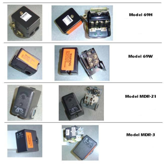
How-To Adjust A Pressure Switch
This short video shows how to adjust a pressure switch.
Pressure Switch Adjustment Procedure
Adjusting pressure switches can be difficult and time consuming unless a uniform and correct approach is used. The following instructions are based on adjusting the most common pressure switches.
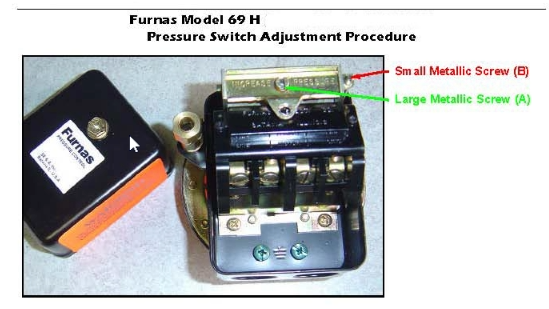
On 69H style switches the large metallic screw (A) is used first to adjust the cut-in pressure (the point at which the compressor comes on as system pressure decreases). The small metallic screw (B) is used to adjust the cut-out pressure (the point at which the compressor shuts off on rising pressure).
The correct procedure is to start with no pressure and energize the circuit. The compressor should start immediately. Allow the compressor to run until it shuts down and note the pressure reading (cut-out setting). Now bleed air out of the system until the compressor restarts and note the pressure reading (cut-in pressure). If the cut-in point is not satisfactory, adjust the large metal screw (A) after the compressor stops (clockwise increases the setting). Repeat the bleeding and adjusting until the cut-in point is correct. Each time the compressor stops note the cut-out point which will be changing each time you adjust the large metallic screw.
After the cut-in point is set to your satisfaction, adjust the small metallic screw (B) to raise (clock-wise raises) or lower the cut-out setting from the last noted reading and repeat the bleeding operation. The cut-in point should remain the same each time.
It is VERY IMPORTANT that the differential between the cut-in and cut-out points is 7 # or more. Below 7 psi, chattering of the pressure switch contacts as the pressure approaches the cut-out point may occur. Chattering will cause the compressor to turn on and off rapidly allowing no time for the motor and pressure switch contacts to cool-destroying the motor in a very short period of time. Chattering can also be especially damaging to a motor starter if one is being used in the circuit.
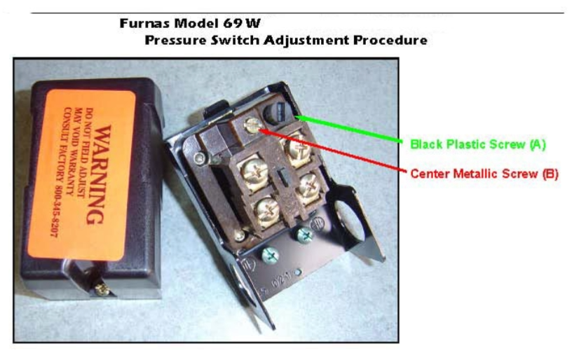
On 69W style switches the center metallic screw (B) is used first to adjust the cut-in pressure (the point at which the compressor comes on as system pressure decreases). The black plastic screw (A) is used to adjust the cut-out pressure (the point at which the compressor shuts off on rising pressure).
The correct procedure is to start with no pressure and energize the circuit. The compressor should start immediately. Allow the compressor to run until it shuts down and note the pressure reading (cut-out setting). Now bleed air out of the system until the compressor restarts and note the pressure reading (cut-in pressure). If the cut-in point is not satisfactory, adjust the center metal screw (B) after the compressor stops (clockwise increases the setting). Repeat the bleeding and adjusting until the cut-in point is correct. Each time the compressor stops note the cut-out point which will be changing each time you adjust the large metallic screw.
After the cut-in point is set to your satisfaction, adjust the black plastic screw (A) to raise (clockwise raises) or lower the cut-out setting from the last noted reading and repeat the bleeding operation. The cut-in point should remain the same each time.
It is VERY IMPORTANT that the differential between the cut-in and cut-out points is 13# or more. Below 13 psi, chattering of the pressure switch contacts as the pressure approaches the cut-out point may occur. Chattering will cause the compressor to turn on and off rapidly allowing no time for the motor and pressure switch contacts to cool-destroying the motor in a very short period of time. Chattering can also be especially damaging to a motor starter in one is being used in a circuit.
Condor Model MDR-21
Pressure Switch Adjustment Procedure
STEP 1: Turn Main Calibration Nuts clockwise to increase cut-in pressure and turn counter-clockwise to decrease cut-in pressure.
STEP 2: Turn Differential Pressure Nut clockwise to increase cut-out pressure and turn counter-clockwise to decrease cut-out pressure*.
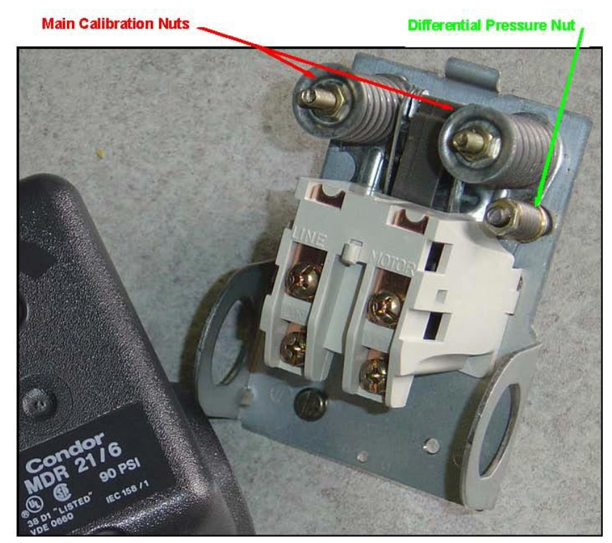
* Differential Pressure is defined as the difference between cut-out and cut-in pressure. Turning the Differential Pressure Nut clockwise increases the Differential Pressure, which increases the cut-out pressure without changing the cut-in pressure.
Condor Model MDR-3
Pressure Switch Adjustment Procedure
STEP 1: Turn Main Calibration Screw clockwise to increase cut-out pressure and turn counter-clockwise to decrease cut-out pressure.
STEP 2: Turn Differential Pressure Screw clockwise to decrease cut-in pressure and turn counter-clockwise to increase cut-in pressure*.
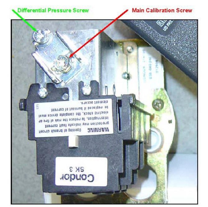
* Differential Pressure is defined as the difference between cut-out and cut-in pressure. Turning the Differential Pressure Screw clockwise increases the Differential Pressure, which increases the cut-out pressure without changing the cut-in pressure.
Recent Posts
-

Setting Up Your Air Compressor for Painting: Beyond Just Pressure
Most DIYers and shop owners think a successful paint job is 90% technique and 10% pressure settings. …Apr 22, 2026 -

Master Your Air Flow: A Guide to Air Compressor Manifolds
In the world of pneumatic systems, efficiency is king. While many DIYers and professionals focus on …Apr 15, 2026 -

How to Prep Your Air Compressor for Peak Performance: The Spring Maintenance Checklist
When the seasons shift, your air compressor faces new challenges. Changes in temperature and humidit …Apr 7, 2026