
Demystifying Air Compressors: A Comprehensive Guide to Understanding the Components
Air compressors are versatile machines that find application in various industries, from manufacturing to construction. Understanding the different components of an air compressor is essential for anyone using or maintaining these powerful devices. In this blog, we will describe the key parts of an air compressor, shedding light on their functions and importance.
Compressor Pump:
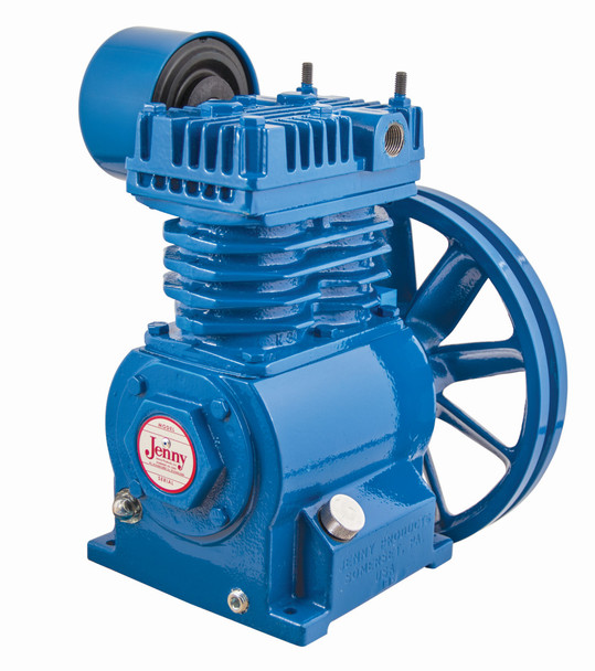
The compressor pump is the heart of an air compressor. It is responsible for compressing the air and delivering it at the desired pressure. Typically driven by an electric motor, yet can also be gas- or diesel-powered, the pump draws in ambient air through an intake valve and compresses it using pistons (reciprocating pumps) or rotary mechanisms (rotary screw pumps).
Motor / Engine:
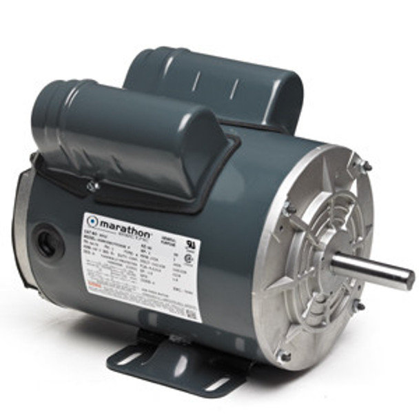
The motor provides the power required to drive the compressor pump. Electric motors are commonly used, although there are models that use gasoline or diesel engines. The motor's horsepower rating directly affects the compressor's performance, determining its ability to deliver compressed air efficiently.
Air Tank:
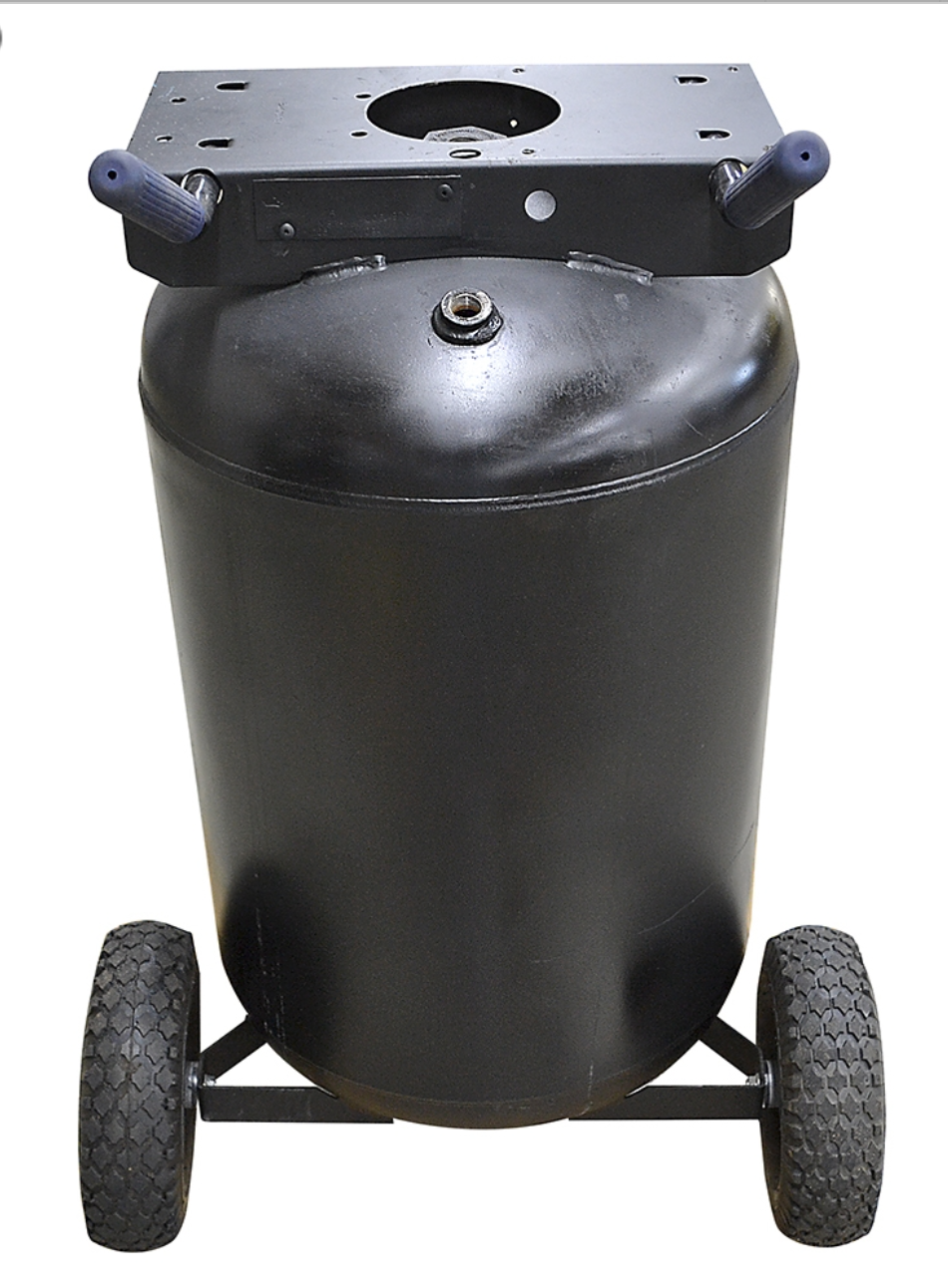
The air tank serves as a reservoir for the compressed air, providing a steady supply during peak demand periods. It allows the compressor to run intermittently, storing compressed air for later use. The tank also helps regulate pressure fluctuations, ensuring a consistent output pressure.
Pressure Switch:
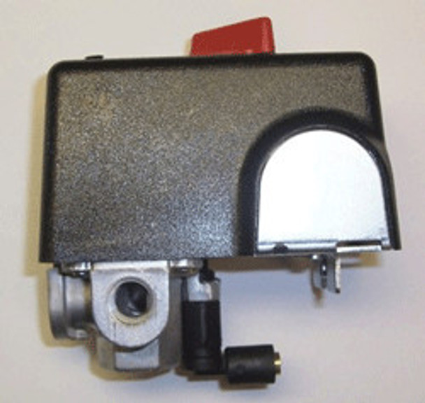
The pressure switch acts as a control mechanism, monitoring the air pressure inside the tank. When the pressure drops below a predetermined level, the switch signals the motor to start, allowing the compressor pump to refill the tank. Conversely, when the pressure reaches the upper limit, the switch shuts off the motor, preventing over-pressurization. The most important specification to look for on a pressure switch is the “cut-in” and “cut-out” PSI it is preset for, depending on the model of the compressor. Usually, you will see a specification such as “95/125 PSI” or 140/175 PSI”, which denotes the cut-in and cut-out pressure the switch is preset for at the factory for a particular air compressor model. Common pressure switch manufacturers are Hubbell, Condor, and Square D.
Safety Valve:
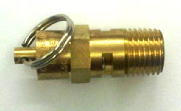
The safety relief valve is a crucial safety feature that protects the air compressor from excessive pressure buildup. It automatically releases air if the pressure exceeds the set limit, preventing potential damage or accidents.
Intake Filter:
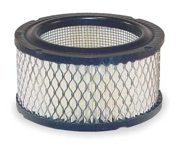
The air intake filter prevents dust, debris, and other contaminants from entering the compressor pump. It helps maintain the efficiency and longevity of the machine by ensuring clean air intake. Regular cleaning or replacement of the filter is necessary to prevent clogging and maintain optimal performance.
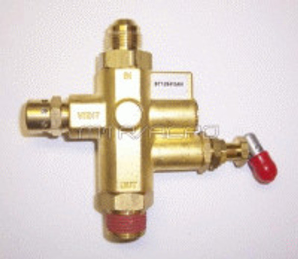
Unloader / Bleeder Valve:
The unloader (or bleeder) valve provides an additional safeguard against over-pressurization and back-pressure. It is designed to release excess pressure from the system after the unit shuts off at the maximum PSI setting, preventing back-pressure to the pump head, and allowing the compressor to restart without pressure on the pump head. The unloader valve is usually located on the side or underneath of the pressure switch on an electric air compressor and is connected either to the pump head or to the side of the in-tank check valve via a small tube (usually ¼” OD). Once the compressor shuts off, the excess air in the airlines is discharged from a pinhole in the side of the valve for a few seconds and then will reseal.
Pressure Gauge:
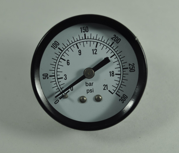
The pressure gauge displays the current air pressure inside the tank. It allows the user to monitor the system's output pressure and adjust it as needed. Proper pressure management ensures that the compressor operates within safe and efficient parameters.
A second pressure gauge is almost always installed on the unit, which is the regulator pressure gauge. This pressure gauge reads the outlet pressure PSI, which is set by the air regulator knob on the compressor. Typically, every compressor is outfitted with an air regulator and gauge, as this “regulates” the exact PSI needed for the specific application the compressor is used for.
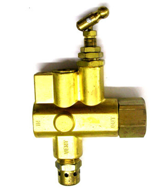
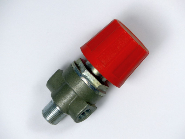
Pilot / Unloader Valve (for gas-powered air compressors):
The pilot/unloader valve is a crucial component found in gas-powered air compressors. It is responsible for controlling the operation of the compressor's unloader mechanism. When the compressor reaches its maximum pressure, the pilot/unloader valve releases the excess air from the compressor head and allows the compressor to restart smoothly for the next cycle. This valve ensures efficient operation and prevents the compressor from starting under load, which could cause damage to the motor or other components.
Air Regulator:
The air regulator is a device used to control and adjust the pressure of the compressed air output from the air compressor. It is typically installed downstream of the compressor and before the point of use. The regulator allows the user to set the desired pressure level for their specific application. By turning the adjustment knob, the user can increase or decrease the pressure output, providing versatility and control over the compressed air flow. The air regulator ensures that the air pressure remains constant and within the desired range for optimal performance of pneumatic tools and equipment.
Motor / Engine Pulley:
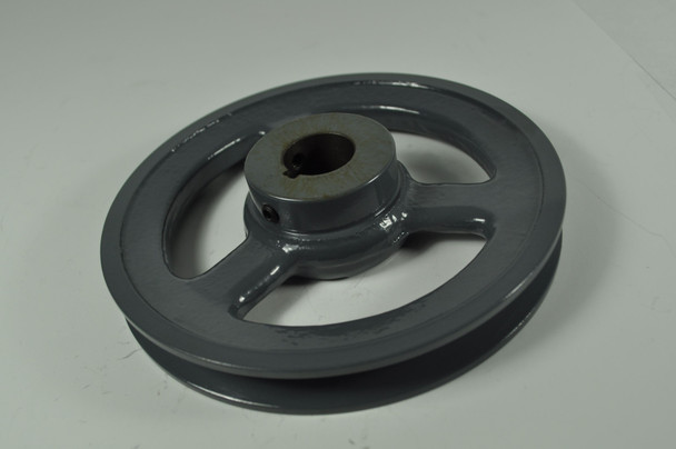
The motor/engine pulley is a component that is part of the power transmission system in an air compressor. It is attached to the motor or engine shaft and is connected to the pump flywheel through a drive belt. As the motor or engine rotates, the pulley transfers the rotational motion to the pump flywheel, which then drives the compressor pump. The pulley's size and ratio determine the speed at which the pump operates, affecting the volume and pressure of the compressed air produced.
Pump Flywheel:
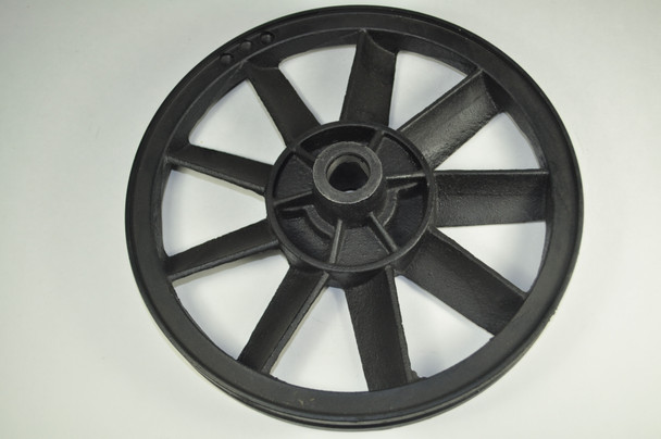
The pump flywheel is a large, disc-shaped component located on the compressor pump. It is connected to the motor/engine pulley through a drive belt. The primary function of the flywheel is to store rotational energy and provide smooth operation by reducing fluctuations in the rotational speed of the pump. It helps to maintain a consistent and steady flow of compressed air by absorbing and distributing the energy generated by the motor or engine. The flywheel also has angled fins to cool the pump during operation. If any fins are broken, replace the flywheel to prevent the pump from overheating.
Understanding the components of an air compressor is vital for efficient operation and maintenance. From the compressor pump to the pressure switch and safety features like the relief valve, each part plays a critical role in delivering reliable and controlled compressed air. By familiarizing yourself with these components, you can make informed decisions, troubleshoot issues, and maximize the performance and lifespan of your air compressor.
Recent Posts
-

Boost Efficiency: The Benefits of Quick-Connect Couplings
Have you ever found yourself wrestling with threaded fittings while trying to swap out air tools, lo …Mar 11, 2026 -

How to Choose the Right Replacement Pump: Oil-Free vs Oil-Bath, CFM, and RPM
Replacing a tired air compressor pump is one of the fastest ways to restore airflow, tool performanc …Mar 3, 2026 -

Power Loss? How to Identify & Replace Worn Air Compressor Piston & Cylinder Kits
If you’ve noticed your air compressor is taking longer than usual to reach full pressure, or if it s …Feb 25, 2026